When engineering high-speed cosmetic manufacturing lines, packaging failure is the ultimate productivity bottleneck. Imagine an automated rotary filling machine operating at 120 units per minute: a slight variance in bottle neck perpendicularity, an unstable base causing conveyor tipping, or an uncalibrated squeeze sidewall can cause line jams, costly downtime, and wasted formulation. The structural engineering behind every custom plastic bottle dictates whether a packaging run proceeds seamlessly or encounters catastrophic production delays. Precision packaging design bridges the gap between aesthetic branding and high-efficiency manufacturing. Packaging stability prevents factory bottlenecks. Packaging precision secures fill-level accuracy. Packaging durability withstands automated torque. Packaging reliability ensures consistent output across every production shift.
Key Takeaways
-
Plastic cosmetic bottles must be engineered around specific industrial filling methods, including piston, rotary gravity, vacuum, and net weight filling lines.
-
Neck finish tolerances (such as SPI/GPI thread standards), anti-rotation lugs, and wall thickness uniformity directly prevent conveyor tipping and capping failures.
-
Polymer selections like Polypropylene (PP), HDPE, and PET deliver tailored mechanical properties for squeeze recovery, top-load crush strength, and chemical barrier resistance.
-
Viscosity compatibility dictates neck diameter and dispensing orifice design, matching ultra-fluid serums or dense emulsion creams to proper nozzle dimensions.
-
B2B OEM/ODM manufacturing protocols require strict pre-fill stress-crack resistance (ESCR) and vacuum decay leak testing to guarantee line reliability.
Engineering Bottle Geometry for Automated Filling Lines
Industrial bottling plants operate on tight mechanical tolerances. When a cosmetic formulation enters the commercialization stage, container geometry must accommodate robotic star wheels, timing screws, indexing conveyors, and pneumatic clamping stations. An aesthetically pleasing shape that fails on conveyor tracks creates immense manufacturing friction. Therefore, structural design must balance visual branding with strict kinematic mechanics.
Conveyor Stability and Center of Gravity Optimization
Empty plastic containers are inherently lightweight and prone to tipping over at high line speeds, especially during transitions across conveyor transfer dead-plates. To prevent the domino-effect line stoppages caused by fallen containers, packaging engineers optimize the bottle's center of gravity (CG). The base-to-height aspect ratio must be calculated with precision; tall, narrow bottles require a weighted push-up base or an engineered perimeter contact rim to maintain dynamic stability along vibration-heavy tracks.
For custom oval, rectangular, or irregular profiles, orientation lugs (puck-locking notches) are molded directly into the bottle bottom or heel. These notches allow high-speed sorting machines and puck systems to align every bottle instantly into the exact rotational angle required for nozzle insertion and label application. Without these geometric guides, asymmetrical containers rotate randomly, causing filling nozzles to strike the shoulder and trigger emergency halts.
Dynamic line stability requires a maximum height-to-width ratio of 3:1 for unpucked containers on high-speed modular tabletop chains, ensuring smooth transport without micro-bouncing.
Furthermore, wall thickness distribution achieved via extrusion blow molding (EBM) or injection stretch blow molding (ISBM) must remain consistent. Uneven resin distribution produces localized weak spots that flex unpredictably under mechanical gripper pressure, leading to fill volume discrepancies or skewed labeling passes.
Top-Load Strength and Capping Torque Resistance
During automated packaging, containers experience substantial vertical and rotational forces. Vertical force peaks during diving nozzle entry and chuck capping, while rotational force concentrates around the neck during high-speed torque capping. If a bottle lacks sufficient top-load crush resistance, vertical pressure causes sidewall buckling and seal failure.
Deploying advanced durable PP bottle solutions and reinforced HDPE shoulder geometries provides high compressive resistance. The bottle shoulder acts as a structural arch, distributing downward forces evenly into the sidewalls. In addition, anti-rotation ribs placed beneath the neck transfer torque directly to the puck or conveyor clamp, eliminating container spin during closure tightening.
|
Container Material |
Top-Load Resistance |
Torque Deformation Risk |
Optimal Line Speed |
|---|---|---|---|
|
Polypropylene (PP) |
High (Elastic Recovery) |
Very Low |
80 – 140 bpm |
|
Polyethylene (HDPE/LDPE) |
Medium (Ductile Flex) |
Low to Moderate |
60 – 110 bpm |
|
PET / PETG |
Very High (Rigid Columnar) |
Extremely Low |
120 – 200+ bpm |
Matching Bottle Architecture to Filling Technologies
Cosmetic filling facilities deploy different machine architectures depending on product viscosity, foaming propensity, and batch volume requirements. Plastic bottle specifications must directly reflect these distinct filling dynamics to maintain line speed and volumetric accuracy.
Piston Filling and Viscous Emulsion Lines
High-viscosity formulations—such as heavy anti-aging creams, SPF sunblocks, and thick clay suspensions—rely on positive displacement piston fillers. Piston pumps inject dense bulk fluid into the container under positive hydraulic pressure. Because of this localized pressure discharge, the bottle must possess an orifice wide enough to allow displaced air to exhaust rapidly around the diving nozzle.
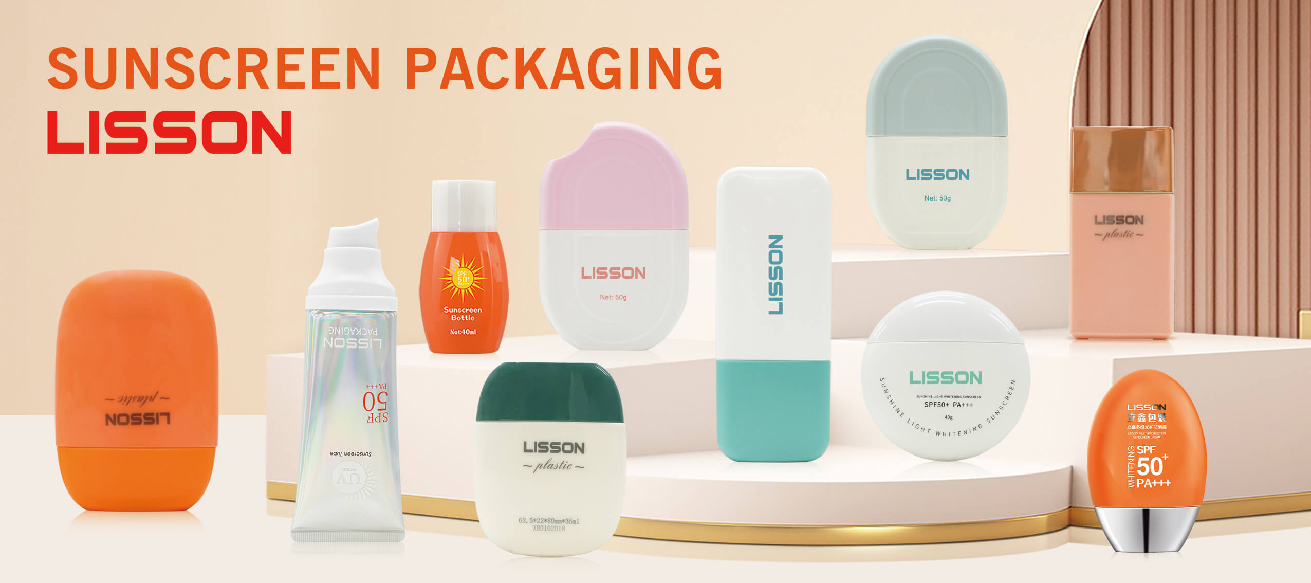
For viscous sunscreen and lotion products, combining optimized internal neck diameters with a dedicated high-performance sunscreen bottle profile prevents backpressure bubbling. If the neck opening is excessively narrow relative to the nozzle diameter, entrapped air will vent violently, creating product blowback, dirty bottle shoulders, and inaccurate fills. Tapered neck transitions help guide viscous product smoothly toward the container base, minimizing internal air voids.
Rotary Vacuum and Overflow Level Filling Lines
Water-thin cosmetic solutions, including balancing toners, micellar cleansers, and setting sprays, are frequently processed via overflow or vacuum filling machinery. Overflow fillers pump liquid until it reaches a designated cosmetic fill line, continuously siphoning excess liquid back into the holding tank. This technique ensures a visually uniform fill height across transparent retail packaging.
However, overflow and vacuum techniques exert slight internal pressure differentials. Thin-walled containers can suffer from paneling—an inward sidewall collapse caused by vacuum suction. To counteract this, structural vacuum ribs, chamfered side panels, or radial reinforcing rings are molded into the container body. These geometric reinforcements maintain structural rigidity during the filling cycle while keeping the container lightweight and material-efficient.
Airless and Piston-Free Bottom-Up Filling
Oxidation-sensitive serums, retinol treatments, and organic skincare formulas utilize advanced airless bottle packaging systems. Unlike standard dip-tube bottles, airless packaging relies on an internal sliding piston that rises as dispensing occurs. The industrial filling process for airless bottles typically utilizes bottom-fill technology, where bulk formulation is injected from the bottom before the base plug is hermetically seated.
This process demands ultra-tight cylindrical bore tolerances along the entire internal chamber wall. Any micro-taper, flash, or surface waviness inside the cylinder will cause fluid bypass around the piston skirt, resulting in atmospheric leakage and mechanism seizure. Precision injection molding ensures the inner chamber diameter remains concentric within micro-millimeter specifications.
Neck Finish Precision, Thread Standards, and Closure Integration
The interface between the plastic bottle neck and the dispensing closure is the most critical engineering zone in cosmetic manufacturing. A failure here leads to torque stripping, crooked cap seating, or liquid leakage during international transit.
|
SPI / GPI Neck Finish |
Thread Configuration |
Typical Packaging Application |
|---|---|---|
|
400 Finish |
1 continuous thread turn (360°) |
Standard screw caps, shallow disc tops |
|
410 Finish |
1.5 thread turns (approx. 540°) |
Standard lotion pumps, fine mist sprayers |
|
415 Finish |
2 full thread turns (approx. 720°) |
High-torque dispensing pumps, travel containers |
Automated Cap-Torque and Ratchet Ring Dynamics
Automatic capping machinery applies rotational torque using servo-driven or magnetic clutch capping heads. If the neck finish dimensions (T, E, I, and H dimensions according to SPI/GPI industry standards) exhibit slight molding shrinkage variations, the capping chuck will either over-torque, stripping the plastic threads, or under-torque, causing container leakage.
Furthermore, when integrating complex lotion pump bottle configurations, the dip-tube length must match bottle internal depth precisely. Automated insertion mechanisms push the dip tube into the container before screwing the collar down. If the bottle base internal dome is improperly calibrated, the dip tube can curl excessively, occluding the intake orifice and preventing full formulation evacuation for the end consumer.
Material Selection and Compatibility in High-Speed Production
The choice of polymer resin does not simply define final tactile feel; it directly governs processing temperature tolerances, mold shrinkage rates, and dynamic chemical resistance during packaging runs.
Molding shrinkage rates range from 1.5% to 2.5% for Polypropylene and HDPE, whereas PET experiences minimal shrinkage below 0.5%, demanding precise mold tooling adjustments for tight-fitting automated line components.
Environmental Stress Crack Resistance (ESCR)
Cosmetics containing essential oils, surfactants, organic alcohols, and active sun filters can act as aggressive chemical stress agents against plastic substrates. When bottles undergo high-speed conveyor gripping and pneumatic torque clamping, localized surface stresses are amplified. If the resin lacks adequate Environmental Stress Crack Resistance (ESCR), micro-fissures develop around the bottle neck or base sprue, causing catastrophic rupture weeks after shipping.
By engineering specialized copolymer blends—such as high-grade Polypropylene (PP) and specialized multi-layer HDPE/EVOH matrices—manufacturers ensure both product compatibility and mechanical durability. These materials maintain structural elasticity during factory clamping and withstand the repeated physical compression required by squeeze bottle mechanics.
Engineering cosmetic plastic bottles for modern filling lines demands a multidisciplinary approach bridging fluid dynamics, mechanical tooling, and polymer science. From center-of-gravity stabilization and top-load crush strength to standardized neck finishes and chemical stress resistance, every millimetric contour impacts overall line efficiency and brand reputation. Partnering with a specialized B2B packaging manufacturer guarantees that your custom containers deliver flawless aesthetic luxury while performing with maximum reliability across every automated production line.
FAQ
Why do plastic bottles tip over on high-speed filling lines?
Bottle tipping is generally caused by an elevated center of gravity, inadequate base diameter-to-height ratios, or base convex deformation. Implementing recessed push-up bases, stabilizing orientation lugs, or modular puck systems ensures complete stability across conveyor transfers.
How does bottle wall thickness affect automated capping?
Uniform wall thickness provides the top-load strength needed to withstand pneumatic capping chuck pressure. Thin or uneven sidewalls buckle under vertical load, causing thread misalignment, loose caps, and compromised hermetic seals.
What neck finish is standard for cosmetic pump dispensers?
The 24/410 and 28/410 GPI/SPI standards are the most common neck finishes for cosmetic lotion pumps and fine mist sprayers. The extra half-turn of thread engagement (compared to a 400 finish) prevents leakage under hydraulic line pressure.
How do viscosity variations dictate cosmetic bottle orifice design?
High-viscosity lotions require wider neck openings to prevent air entrapment and backpressure blowback during high-speed piston filling. Thin, water-based solutions can use narrower openings compatible with vacuum or overflow nozzles.
What is the advantage of using PP material for automated squeeze bottle lines?
Polypropylene (PP) provides outstanding hinge memory, high elastic recovery, and superior resistance to environmental stress cracking (ESCR). It absorbs mechanical conveyor shocks without cracking and reliably recovers its shape after automated clamping.